
Last time I talked about how information is passed to a BPMN process from outside. All modelers need to understand that. This month I'm going to talk about data inside a BPMN process.
If you are a typical process modeler, this is something you can usually safely ignore, because it pertains only to executable models. But recently it came up in a question from a former student, and I see there was also some recent discussion of it on LinkedIn, where my name was invoked. The question concerns what the BPMN 2.0 spec says, always an iffy proposition, since much of my Method and Style approach was developed as a way to "bend" the rules of the spec - which focus on executable BPMN - to the needs to most process modelers. As I said, most process modelers ignore execution-related issues altogether, since making BPMN executable in practice means turning it over to Java developers, who themselves ignore what the spec has to say. But recently, I have become more interested in executable BPMN, as the Trisotech tool evolves to make it more accessible to non-programmers by borrowing FEEL and boxed expressions from DMN but otherwise staying true to the BPMN spec. I believe that BPMN users will increasingly be interested in the possibility of executing their models, ideally in an interchangeable way, so the topic is timely.
In an executable process, variables are represented in the diagram as data objects, with the dog-eared page icon. In BPMN 1.x, data objects were effectively annotations simply indicating some kind of data, but in BPMN 2.0 they became program variables in an executing process, which made them less useful in non-executable models. You can think of them as in-memory storage of instance data. Data developed by a process task or received as a message may be stored in a data object and later passed on to another task or message. This passing of information to and from a data object is indicated in the diagram as a data association, discussed last month in the context of data stores. A data association does more than communicate the information; it also provides a mapping between the format of the data object and the format of the task or message at the other end.
The question that caused all the kerfuffle on LinkedIn was not about data objects per se, but data inputs and data outputs - the things at the other end of a data association. What are they? I think from the spec it's obvious, but I remember having this same argument with Camunda seven or eight years ago, so I guess not obvious at all. Data inputs and outputs describe the interface of a task, event, or process. They are not variables, i.e., they do not store values. They merely specify the name and type of the parameters that must be supplied on input or are returned on output. The data inputs and outputs of a task or event has no visualization in the diagram, but those of a process do. It looks just like a data object but with an arrow symbol inside, white for data input and black for data output. This is potentially a source of confusion: A data input shape connected via data association to a task is not a data input of the task. It is a data input of the process that is mapped to the (unvisualized) data input of the task.
Technically, a task's ioSpecification describes its interface as one or more input sets and one or more output sets. Each input set contains pointers to data inputs, defining the name and type of the input parameters, and similarly for each output set. When a sequence flow arrives at the task, the task waits for values to be supplied to its input sets and once one of them is fully satisfied begins execution. I've never heard of a task with more than one input set or output set, but I guess they wanted to be prepared for anything.
This is easier to understand by looking at an example.
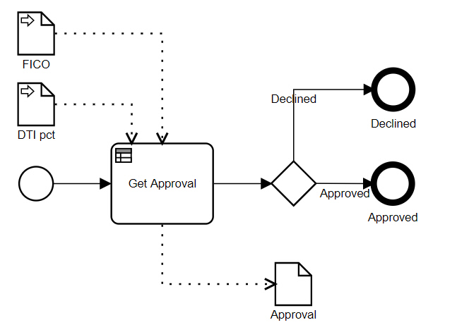
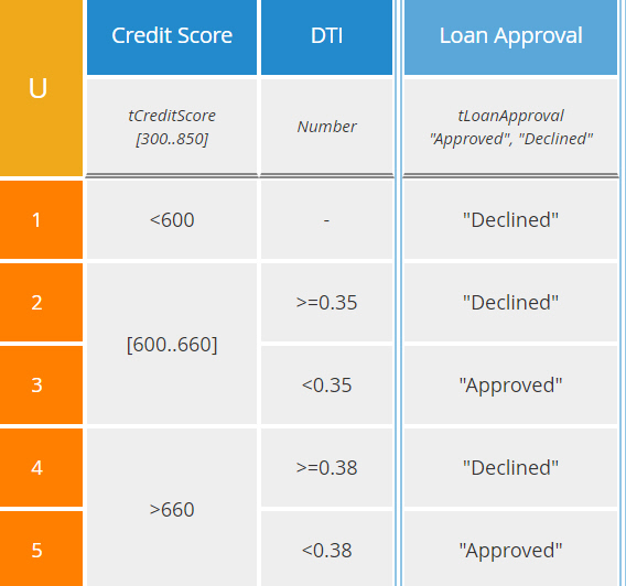
Here we have a simple process, a single decision task (aka business rule task) Get Approval followed by a gateway that branches to one of two end states. A decision task invokes a DMN decision service, here the one called Loan Approval shown below:
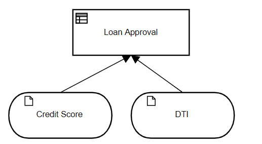
From the BPMN diagram, we see the process has data inputs FICO, representing the credit score, and DTI pct, representing the debt-to-income ratio expressed as a percent. For a decision task, the task data inputs are the parameters of the decision service, which are the input data elements of the decision model: Credit Score and DTI, where the latter is expressed as a decimal number not a percent. Note that these task data inputs do not appear in the BPMN diagram.
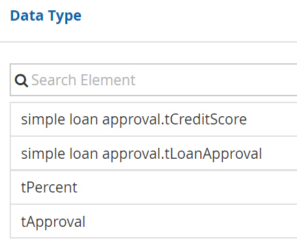
To make this process executable, we need to publish the decision model, which creates a decision service, and then bind the BPMN decision task to it. When we do that, we see that the decision service and its datatypes are imported into the BPMN model with the prefix simple loan approval:
Now, for the decision task, select Data Input Mapping, and we fill in the following boxed expression, a context:
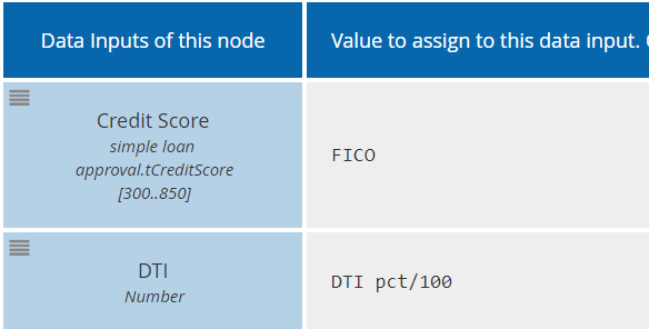
At last, visualization of the task data inputs! Not in the BPMN diagram, but in a boxed expression mapping process data - either process data inputs or data objects - to the data inputs of the task. The task data inputs are in the first column. They are defined by the decision service; the modeler cannot edit them. The second column is a FEEL expression mapping process data to each task data input. Note that the name of the process data element need not match that of the task data input, and the value need not match either. Here we had to convert DTI pct, expressed as a percent, into DTI, expressed as a decimal number. Similarly, we see the task data outputs via the Data Output Mapping:
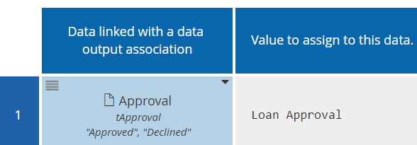
Here the first column is a process data element from the BPMN diagram, either a data object or process data output. In this case it's the data object Approval. The second column is an expression of the decision service outputs, in this case the value of the decision Loan Approval.
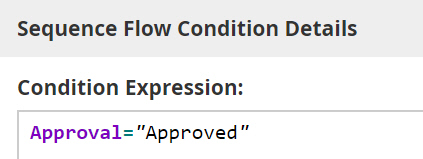
The data object Approval now holds the output of the decision, and it can be tested by the gateway. In Method and Style, which doesn't use data objects, the end states of the task are implied by the gate labels, but in executable BPMN we ignore those and specify the gate conditions as FEEL expressions of process data. Selecting the "Approved" gate, we define the condition as Approval = "Approved", where Approval is the process data object, and similarly for the "Declined" gate.
This simple example illustrates the interaction between process data inputs, data objects, and task data inputs and outputs in an executable process. All of it is background to the question that started this post, which I have not yet explained.
That question was whether or not a subprocess has data inputs and outputs. The answer, as stated explicitly in the spec, is No. A process has them (visualized in the diagram) and a task has them (not visualized in the diagram), but a subprocess does not have them at all! Personally, I don't care for that answer, but then again, I find a lot of what the spec says about subprocesses to be problematic. For example, it says subprocess start events may have incoming sequence flows arriving from outside the subprocess, and there could be more than one of them! Nonsense like this is what motivated Method and Style a decade ago, so please don't ask me to defend it.
I've tried to think about what might have been the motivation behind denying data inputs and outputs to subprocesses while granting them to tasks. In executable BPMN, a user task, service task, or decision task effectively represents a service request issued by the process engine to a resource performing the task. The task data inputs (technically, the input sets) define the information required by that resource in the service request. (A send task, receive task, or script task is performed entirely by the process engine without involving a resource.) A subprocess, however, is not a single thing performed by a resource. It is a collection of things each performed by a resource, almost as if it were conceived as simply a drawing aid to reduce the complexity of the diagram. But obviously, a subprocess is far more than this. In the metamodel, a subprocess "owns" its child elements; a task cannot belong to more than one subprocess. Also, a subprocess defines the scope of events modeled on its boundary or as enclosed event subprocesses. A subprocess even defines the scope of a contained data object, which is accessible only to its descendant process levels.
For all these reasons, it seems to me that subprocesses are first-class modeling objects and denying them data inputs and outputs makes no sense. It means that if the subprocess is drawn collapsed, as it is in parent-level diagrams, you cannot depict the data flow into or out of the subprocess. It would be better, in my view, if BPMN allowed data inputs and outputs in subprocesses, visualized in the child-level diagram just like process data inputs and outputs, and allowed data associations to connect to collapsed subprocess boundaries. But that would require a metamodel change, so it's not going to happen. Instead, if you want to visualize data flow to or from a collapsed subprocess, you'll need to use a directional association connector, as we showed last month with black-box pools. It looks exactly the same, but it has no execution semantics. This works visually, without violating the spec.


Learn how it works
Request DemoConfirm your budget
Request PricingDiscuss your project
Request Meeting